THEORY AND PRACTICE
FREQUENTLY ASKED SEISMIC QUESTIONS
Q. What is a seismic wave?
A. A seismic wave is the transfer of energy through elastic earth materials by way of particle oscillation/vibration.
Q. What are the different types of seismic waves?
A. There are four main types of seismic waves, each characterized by its specific particle motion:
-
Compressional or “p” waves are identical to sound waves – the particle motion is parallel to the propagation direction:
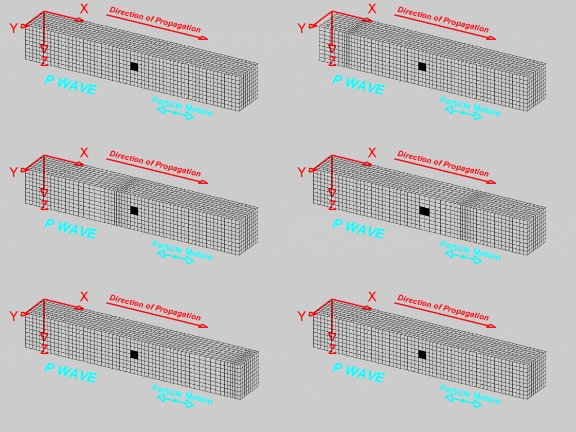
p-wave animation by L.W. Braille, Purdue University, http://web.ics.purdue.edu/~braile/edumod/waves/Pwave.htm
-
Shear or “s” waves are characterized by particle motion that is perpendicular to the propagation direction:
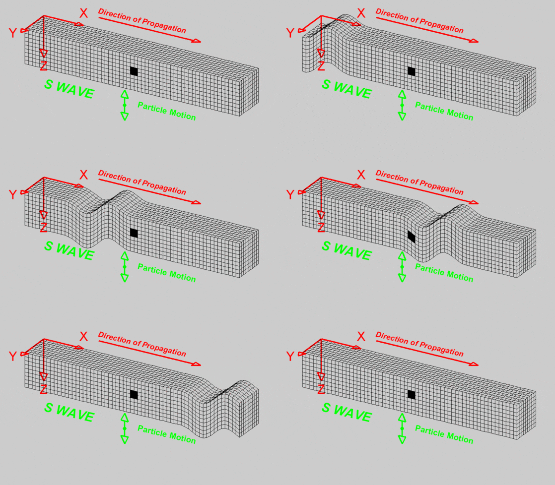
s-wave animation by L.W. Braille, Purdue University, http://web.ics.purdue.edu/~braile/edumod/waves/Swave.htm
Taken collectively, p- and s-waves are known as “body” waves. The velocities of both can be measured via seismic refraction.
-
Surface waves, as the name implies, travel primarily along the ground surface; amplitudes decrease rapidly with depth. There are two types of surface waves. Like body waves, they are characterized by particle motion.
"Rayleigh" waves are characterized by elliptical motion perpendicular to the surface:
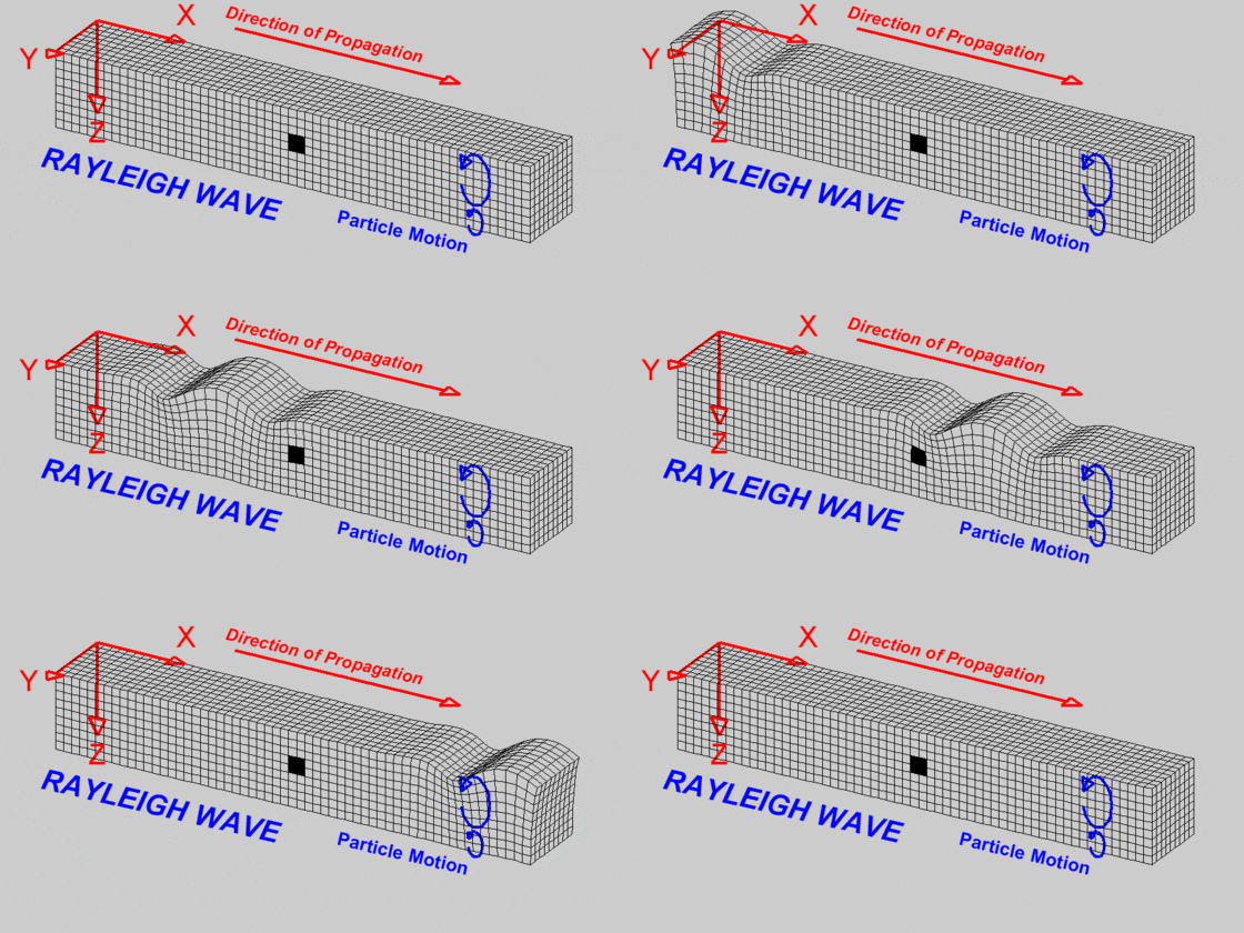
Raleigh-wave animation by L.W. Braille, Purdue University, http://web.ics.purdue.edu/~braile/edumod/waves/Rwave.htm
In the near surface, this motion is “retrograde”, meaning that it is counter-clockwise when the propagation is left-to-right. At depth, the motion can reverse to prograde.
Particles affected by "Love" waves vibrate perpendicular to the propagation direction:
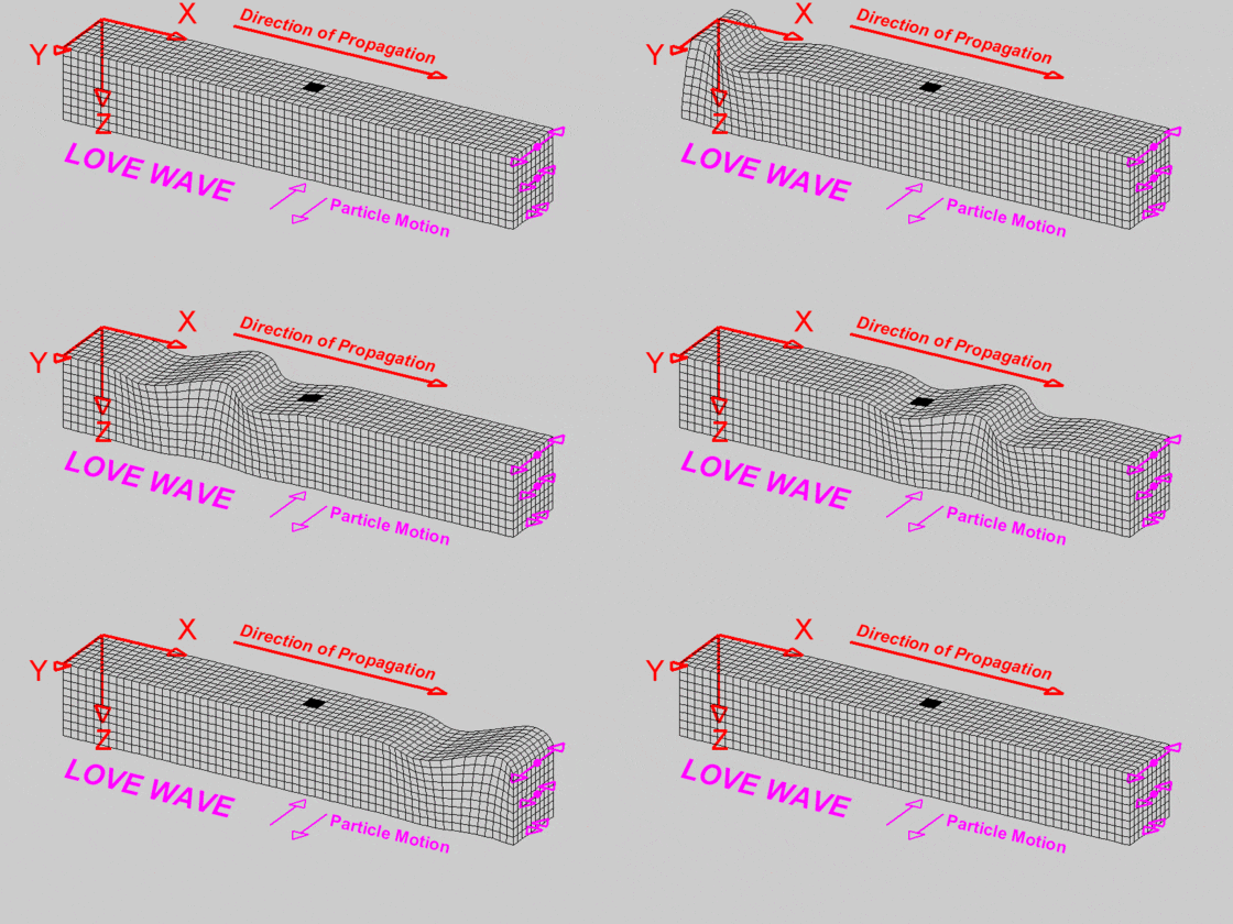
Love-wave animation by L.W. Braille, Purdue University, http://web.ics.purdue.edu/~braile/edumod/waves/Lwave.htm
While the particle motion is similar to that of shear waves, Love wave amplitude is much higher and decreases rapidly with depth. Love waves are the most destructive waves in earthquakes because of their high amplitude and transverse particle motion.
While the various wave types shown above have been isolated for illustration purposes, all are present to some degree whenever seismic energy is travelling through a perfectly-damped solid medium. Actual particle motion is extremely complex.
Q. How fast do seismic waves travel and what controls this?
A. Different types of seismic waves travel at different velocities through any given material. In addition, different materials have different seismic properties, meaning that any one wave type can have a wide range of velocities, depending on the material properties. For instance, the p-wave velocity of shale can range from 800-3,700 m/s. Granite can range from 4,800-6,700 m/s. Because of this, by themselves, seismic velocities alone are not particularly diagnostic with regard to rock type.
Ultimately, seismic velocity depends on the density and elastic properties of the material, whatever its composition. Specifically,
compressional-wave velocity depends on the “incompressibility” of the material, as embodied in the bulk modulus. The higher the bulk modulus, the less compressible the material, and the higher the p-wave velocity. Sound travels through water about four times faster than it does through air. Similarly, shear-wave velocity depends on the rigidity of the material, or the resistance to shear. The higher the shear modulus, the higher the s-wave velocity. Mathematically,

where
K = bulk modulus
µ = shear modulus
ρ = density
Note that Vp depends on both the bulk and shear modulus, while Vs depends only on the shear modulus. This observation implies two things:
-
Shear waves always travel slower than compressional waves through a given material, and
-
Materials with zero rigidity – i.e., fluids – do not carry shear waves at all. Therefore, the absence or presence of groundwater has no effect on the shear wave velocity. It is interesting to note that, in general, seismic velocity increases with density – denser rocks tend to be much harder and faster. Yet in the above equations, density is in the denominator. This is known as the “velocity-density paradox”, the answer to which can be found in the fact that the elastic moduli tend to increase with density as well, and at a faster rate.

Q. What is a [seismic] wave front?
A. A seismic wave front emanates from an energy source like ripples on a pond, but in three dimensions. It is the surface connecting points of equal travel time from the source. In a homogeneous medium, a surface drawn through points of equal travel time is spherical, as depicted in the animation below:

The seismic trace, which is what is recorded by the seismograph, represents particle motion vs. time. In a homogeneous medium, the wave front can also be described as a surface of constant phase:

Q. What is a [seismic] ray?
A. A seismic ray, or “wave front normal”, is an arrow drawn perpendicular to the seismic wave front to indicate the propagation direction at that point on the wave front. It is a convenient tool to help understand wave propagation through layered media; it is not something that exists in a physical sense.

Q. What is Huygen's Principle?
A. Huygen's Principle can be stated in many ways. The simplest definition states that every point on a wave front can be thought of as a new point source for seismic waves.

With a little thought, this may seem obvious, but this realization is extremely useful for understanding the concept of refraction. This, in turn, is essential to becoming a good seismic practitioner.
Q. What is the Reflection Coefficient?
A. The Reflection Coefficient R between two velocity layers is expressed as
R = (ρ2V2 - ρ1V1) / (ρ2V2 + ρ1V1),
Where ρ = density and V = velocity. The quantity ρV is the seismic impedance of the material. The Reflection Coefficient is therefore the difference in seismic impedance over the sum of seismic impedance of two materials. From the above equation, it is apparent that R will be a positive number when V2 > V1, and a negative number when V2 < V1. A positive R means that the polarity of the reflected wave will be the same as that of the incident wave. A negative R means that the polarity of the reflected wave will be the opposite of the incident wave.
It should also be apparent that the larger the contrast in seismic impedance, the larger the amount of incident energy that is reflected (and the smaller the amount that is transmitted).
The above assumes normal incidence. For incident angles other than 90 degrees, the equation is more complex.
Q. What is [seismic] refraction?
A. All wave phenomena, the most familiar being visible light, are subject to refraction, or a change in propagation direction, at interfaces between materials of contrasting propagation velocities. The bigger the difference in velocity, the more the energy is refracted or "bent". As the name implies, seismic refraction uses the travel times of refracted seismic energy to determine the seismic velocity of the earth. A short practical discussion of seismic refraction can be found here.
The most important thing to keep in mind when learning how the seismic refraction method works is this:
When doing seismic refraction, we are only interested in first-arrival energy at each geophone. The rest of the wave train -- reflected energy, surface waves, etc. are discarded and ignored. Except in the exceedingly rare case where the near-surface is slower than the speed of sound in air, the first-arrival energy will always be either direct or critically-refracted energy.
Q. What is seismic refraction used for?
A. Common applications include:
-
Estimating rippability prior to excavation
-
Mapping depth to bedrock/bedrock topography
-
Mapping depth to ground water
-
Measuring the thickness of the weathering zone
-
Calculation of elastic moduli/assessment of rock quality
-
Mapping thickness of landslides
-
Identification and mapping of faults
Q. What kind of waves does seismic refraction use?
A. Seismic refraction uses body waves, most commonly, p-waves. Shear-wave refraction can also be done, but it has become largely supplanted by MASW.
Q. What are the key components of a seismic refraction system?
A. Key components include:
1) Seismograph (StrataVisor, Geode, ES-3000, SmartSeis)
2) 12V Battery
3) PC (Geode and ES-3000)
4) Digital cables (Geode and ES-3000)
5) Geophones (including spares)
6) Geophone cable(s)
7) Source (hammer, weight drop, explosives)
8) Striker plate (if using hammer)
9) Hammer switch and spare
10) Trigger extension cable
11) Measuring tape
12) Hand level
13) Hearing protection (IMPORTANT)
Q. How many people are required for a refraction survey?
A. In general, two people can get the job done. If you are using explosives or a weight drop, a third person may be required.
Q. What geophones should I use in a refraction survey?
A. 10-14 Hz are the most common and the least expensive. Much more than 20-30 Hz and you start cutting into your signal. Less than 10 Hz and the phones become a somewhat fragile and less field-robust.
Q. How do I conduct a seismic refraction survey?
A. A step-by-step field tutorial can be downloaded here: Seismic Refraction Tutorial.
You may find this survey design spreadsheet handy: Refraction Survey Design Spreadsheet.
Click here for a series of videos showing how to conduct a seismic refraction survey.
Q. What is Snell’s Law?
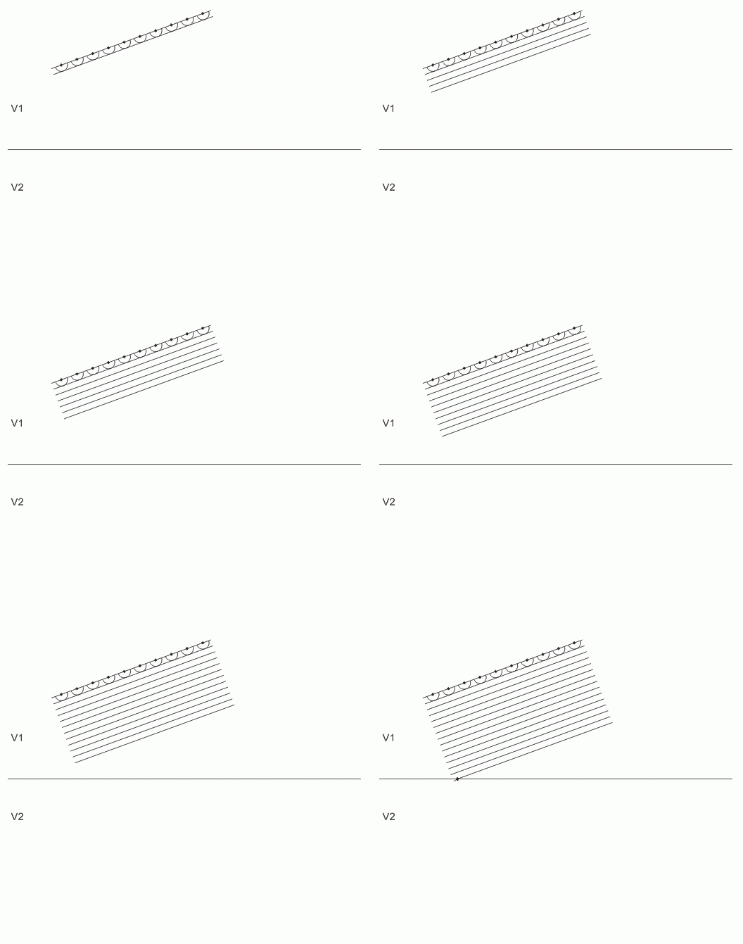
A. Snell’s Law describes quantitatively how wave fronts refract or "bend" at boundaries between contrasting velocities. You've seen it manifest in light waves by the apparent bend of the straw in your glass of water; light travels slower in water than it does in air. Refraction is well illustrated using Huygen's Principle. Consider a wave front (for our purposes, a seismic one) emanating from a point energy source, as shown in the animation above. For simplification, assume we are far enough from the energy source that the wave front is essentially planar, and is approaching an abrupt change in seismic velocity:
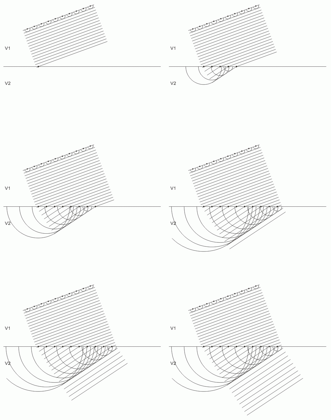

Applying Huygen's Principle, we see that after time t, the plane wave has advanced a distance dequal to the radius of a series of spherical wave fronts emanating from the plane wave:

The radius of the spheres, i.e., the distance the plane wave travels in time t, is equal to V1t. The tangent to the spherical wave fronts is the new position of the plane wave. The planar wavefront continues at velocity V1. Again applying Huygen, we see that "every point on the wave front" (see discussion of Huygen) includes the points where the wave front intersects the velocity boundary:
As the planar wave front advances, the velocity boundary becomes a new source of spherical wave fronts expanding at V2. Hence, part of the plane wave (the tangent to the spherical wave fronts emanating from the velocity boundary) is now traveling at V2. Note that within V2, its direction of advance has changed. This is because in V2, which is higher than V1, Huygen's spheres grow faster during time t:
The refracted wave front continues in the new direction until another velocity boundary is encountered. Here is a simplified version at higher speed:

Zooming out, we see the effect of this on a spherical wave:
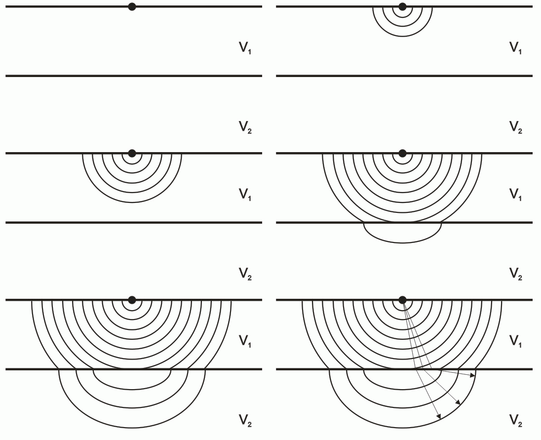
It should be obvious from the above that in order for a wave front to refract, it must strike the velocity boundary at an angle other than 90 degrees. It should also be obvious that in the case of V2 < V1, refraction will be in the opposite direction, and if V2 = V1, no refraction will occur.
Snell's Law quantifies refraction in terms of angle of incidence and velocity contrast. Combining the above diagrams and adding rays,

we can now describe Snell's Law:

In the figure above, i is the incident angle, and r is the refracted angle, measured between the ray and a line perpendicular to the refracting interface. In the example above, the velocity contrast is positive; V2 > V1. There are numerous derivations of Snell's Law on the web if you wish to understand the math.
From the equation, you can see that for any given positive velocity contrast, as i increases, r increases faster:

This is important; it is the property of refraction that allows us to use refracted energy to measure subsurface velocities.
Conversely, a negative velocity contrast results in refraction in the opposite direction:

Q. What is "critical refraction"?
A. In seismic refraction, we are only interested in energy that is critically refracted. This is energy that refracts along the velocity boundary. The angle of incidence that results in critical refraction is called the "critical angle", ic. The critical angle of incidence is the incident angle for which the angle of refraction, ir, is 90°. Substituting 90° for r in Snell's Law shows that


The critically-refracted energy travels at the higher of the two velocities. Huygen's Principle means that every point along the refractor is a point source of energy. That means that some of the critically-refracted energy is returning to the surface. It is easy to show that energy that returns to the surface at ic is the first energy to arrive at the geophone, once the crossover distance is reached.
Q. What is the "crossover distance?"
A. The crossover distance Xc is the distance from the source at which the critically-refracted energy from the next deepest layer overtakes the critically-refracted energy from the previous layer (in the two-layer case, the energy traveling through layer 1 is direct, not refracted energy, but the idea is the same). This is illustrated by the following animation:
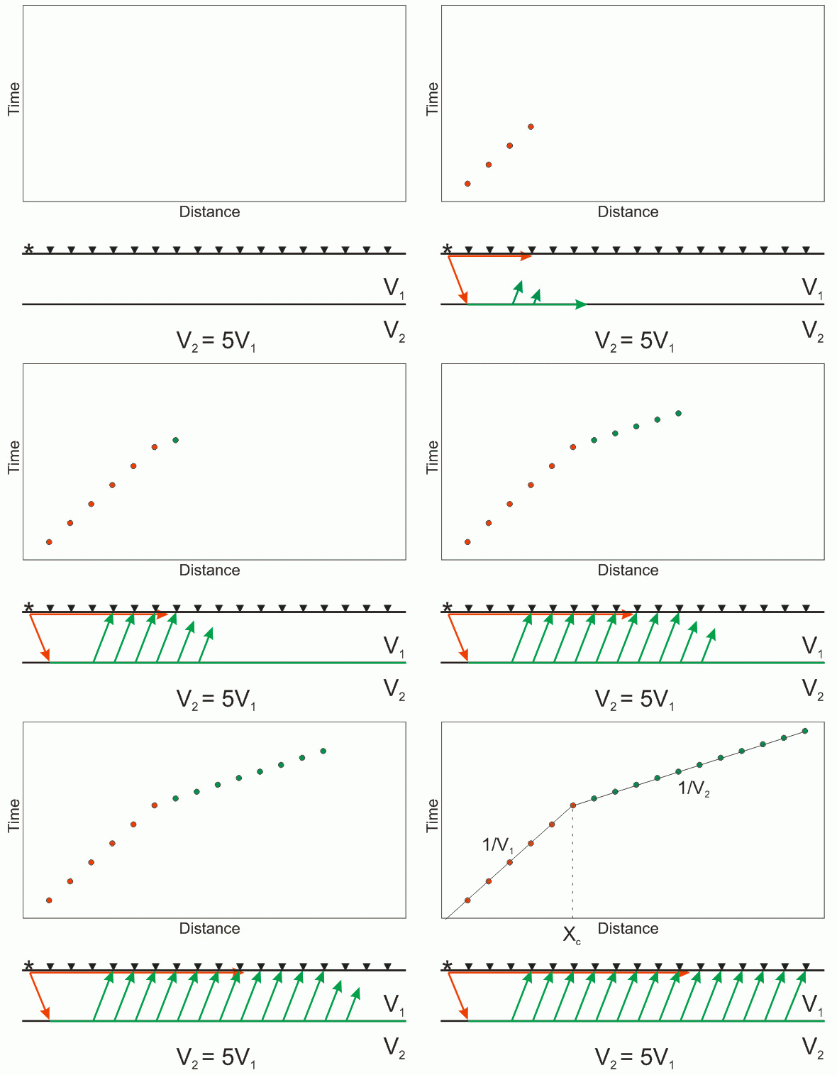
The direct energy (red) is the first-arrival energy at the first six geophones. However, by the seventh geophone, the direct energy is overtaken by the critically-refracted energy (green). The reciprocal of the slope of each segment is equal to the apparent velocity of the material. If there were a third, even faster layer, a third slope and second crossover distance would eventually appear on the travel time graph. The crossover distance, along with the velocities indicated by the slopes of the segments, are used to determine the refractor depth.
Q. What is "apparent velocity"?
A. This is the velocity that is measured directly from the travel time plot, uncorrected for any refractor dip relative to the surface. The apparent velocity is equal to the true velocity only when the refractor is parallel to the surface. If the refractor is dipping, the apparent velocity measured in the updip direction will be higher than the true velocity, and that measured in the downdip direction will be lower. The true velocity, especially for small dips, is close to the average of the updip and downdip velocities, although not mathematically so.
Q. What is a "velocity inversion"?
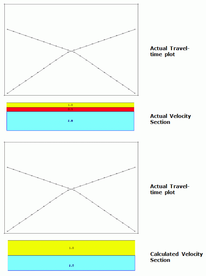
A velocity inversion refers to the case when seismic velocity decreases, rather than increases, with depth. When this happens, energy refracts away from the normal:

This means that no information from the refracting interface returns to the surface, hence no information is gained about that interface, even its very existence.
This is demonstrated by the animation below. There are three distinct velocity layers, but Layer 2 is lower in velocity in Layer 1. The result is a travel time curve that indicates the presence two layers -- layers 1 and 3. Layer 2 is not sampled, so there is no evidence of its presence in the record. However, the presence of Layer 2 does impact the travel time plot by moving the crossover distance out farther than it would be otherwise. The result is that not only is Layer 2 not detected, but the depth to Layer 3 is incorrect -- it is calculated to be deeper that it is.
Q. What is "reciprocity"?
A. The Principal of Reciprocity states that the time required for seismic energy to travel between two points is independent of the direction it is traveling. In other words, if it requires time T to travel from source to geophone, it will require the same time T if the source and geophone are interchanged. While this may seem trivial, it is an important concept in seismic refraction. The reciprocal time is used in the depth calculation and it is an important QC check in the field.

Q. Can I do refraction on pavement?
A. It is exceedingly difficult to do this, because the pavement is generally has a much higher velocity that the materials below it. It is generally not recommended.
Q. Can I do refraction on a hillside?
A. Yes. The slope of the surface is not relevant (at least in theory, although there are obviously practical limits).
Q. How deep can I explore with seismic refraction?
A. Fundamentally, there is no limit. Seismic refraction has been used to image the MOHO. The depth of investigation is governed by the size of the source you use and the length of the seismic spread, which needs to be 4-5 times the depth of investigation.
In practice, the most common use of seismic refraction is in shallow geotechnical, engineering, and groundwater investigations. Most of this is focused on the upper 20 meters or so. It is no coincidence that this happens to be around the upper limit of what can be accomplished with a hammer and plate. Every site is different – the specific geology and amount of cultural noise are important variables that ultimately govern depth of investigation for any given source – but 20 meters for a hammer and plate is a good rule of thumb.
In general, deeper work requires larger sources such as accelerated weight drops or light explosives. The only way to know for sure is to lay out your spread and see if you can get quality first breaks at the far geophones with 8-10 good swings with a sledgehammer.
Q. Is it necessary to bury the geophones?
A. This is rarely necessary or helpful, even in high noise conditions. If you are having difficulty with air waves, burying the geophones might blunt their effect.
Q. What is an “air wave”?
A. An air wave is simply the sound or acoustic wave created by the source, which by definition is what travels through the air rather than the ground. It is what you hear. In most cases, the seismic velocity of the near surface materials his higher than the velocity of sound in air. But in some cases the air wave is faster, and can arrive at the geophones before the seismic first break. This can make the first breaks difficult to pick.
An example of an air wave is shown below. The traveltime graph of an airwave is linear, and will be about 330m/s. It is generally lower in amplitude and higher in frequency than the first break, and can generally be dealt with in processing using a low-cut filter.

Q. Can I do seismic surveying in the rain?
A. Rain won’t hurt the seismographs. If you are using a StrataVisor or SmartSeis and it starts raining, they should be fine as long as they are kept vertical, with the screen pointing up. But acquiring data in the rain should be avoided, especially if there is lightning. Even in the absence of lightening, rain can be a significant source of noise, especially those raindrops striking the geophones directly. Obviously, the harder the rain, the more noise. If waiting the rain out is impractical, shielding the geophones themselves can reduce the noise significantly. If for some reason the seismic system must be left on the ground during an electrical storm, it is advisable to disconnect the trigger and geophone cables from the seismograph.
Q. What is the procedure for doing a seismic refraction survey?
A. The procedure varies depending on the site and the goals of the survey, but a typical step-by-step procedure can be downloaded here. A video tutorial can be found here. Click here for a seismic refraction planning spreadsheet.
Q. Is "mini Sosie" supported? When should I use it?
A. Surveying using a randomized impulsive source (called "mini-Sosie"), such as a construction tamper or "Wacker", is supported by the StrataVisor NZ and the Geode along with the Urban Seismic software and hardware package. The manual can be found here.
In general, mini-Sosie surveying is useful in noisy, urban environments, particularly in close proximity to roads where near-field noise suppression can be used effectively.
Q. What is the best seismograph for seismic reflection?
A. While any Geometrics seismograph can be used to conduct a reflection survey, the Geode was designed specifically with reflection in mind. It includes hardware and software features and greatly facilitate reflection work, CDP reflection in particular.
Q. What source should I use for seismic reflection?
A. The best source for seismic reflection is not always the most practical. Parameters such as cost, size, access, surface materials, and depth of penetration must all be taken into account. As always, a sledgehammer supplies the most bang for the buck when practical. If the ground surface is too soft for a sledgehammer, you might consider a downhole seisgun. Small explosives are ideal in terms of portability and power, but for obvious reasons are often not feasible. Less portable sources like weight drops or vibrators should be considered when access allows and required depth of penetration exceeds that of a sledgehammer, seisgun, or mini-Sosie. Although depth of penetration varies widely depending on the geology and cultural noise, you can expect to see somewhere in the range of 0.25 - 0.5 seconds with the latter three sources.
Q. Which geophones should I use for seismic reflection?
A. The de facto "standard" for high-resolution reflection is 40-Hz geophones. The 40-Hz cutoff will filter out much of the ground roll, allowing you to use the maximum gain even at near offsets, and taking advantage of the full dynamic range of the recording system.
Q. Do I need a roll switch for seismic reflection?
A. A mechanical roll switch is not needed. You can use the electronic roll capability built in to the Geode acquisition software.
Q. How many channels do I need for seismic reflection?
A. There is no one right answer to this question. The higher the channel count, the higher the fold (for any given shot interval), and they higher the signal/noise ratio. For land seismic, we generally recommend 24 or higher-fold data. If the shot spacing is equal to the geophone spacing (typical), this means that you must record on at least 48 channels with each shot. In addition, you must have extra channels for electronic rolling. Taken together, this means that for land CDP reflection, you should have a minimum of 72 channels, which will allow you to roll 48 live channels through a total of 72.